Sunday, December 16, 2012

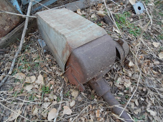
Pump jack--many with mills over them.

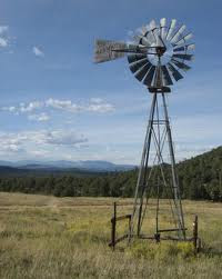
Early Monitor

EXPLODED ILLUSTRATION OF THE IRON MAN 8ft (2.4M) TO 16FT (6M) WATER PUMPING WINDMILL

http://www.ironmanwindmill.com/water-pumping-windmill-exploded-view-small.htm


Sent from my iPad

Wind mill water pump home made P#1.

Check out this video on YouTube:

http://www.youtube.com/watch?v=FNt1OIbsc8Q&feature=youtube_gdata_player


Sent from my iPad

monitor windmill -

http://www.google.com/search?q=monitor+windmill&hl=en&tbo=u&tbm=isch&source=univ&sa=X&ei=KnnOUPKeOejy2QXHooDgBg&ved=0CDEQsAQ&biw=1024&bih=690#biv=i%7C6;d%7CEy0SoZauqnA8UM:


Sent from my iPad

WATER PUMPING WINDMILL HISTORY IN AMERICA

http://www.ironmanwindmill.com/windmill-history.htm


Sent from my iPad

The Mill --Baker

http://www.ftgnewmediainc.com/family/html/the_mill.html


Sent from my iPad

Thursday, December 13, 2012

Open belt driven pump jack

Another view

Bit/ reamer

Steel tower--open side--legs 2 inch drill stem

Rear end drill rig showing mud pump

30 foot steel tower --legs drill stem--open side

Submersible for stock watering

They are installed on 1 inch black plastic, or 1 inch galvanized pipe, or 1 inch solid plastic in 21 foot joints. Those on one inch black plastic use safety rope attached to pump. Tape with electrical tape every 5 feet the wire & safety rope. The lower clamps should be taped also. Wires should be crimped with crimping tool and heat shrink tube applied over connection. Since they are not used with pressure tank & therefore aren't protected from cold, they need weep holes about one foot to 1.5 feet below top.

Drilling rig plus head installer

Wednesday, December 12, 2012

Another view

Well puller

Well driller & mill head installer

Dempster videos has lots of great videos of various mills!!

Great viewing!!

Dempster windmill

Check out this video on YouTube:

http://www.youtube.com/watch?v=a9yukqX4qR4&feature=youtube_gdata_player


Sent from my iPad

Pump rod relief between mill & well rod

In the event of weep hole plug up, this relief will help avoid damage to head, rod , well pipe in event of freeze up. A 12 in chain will work fine or a 12 inch cylinder with plungers on both ends connected by 7/16 rods inserted between mill rod & well rod.

Tuesday, December 11, 2012

Dutch Delta Jr.

Dutch Delta

Dutch Industries - Dutch Delta Jr Windmill

http://www.dutchopeners.com/dutch-delta-jr-windmill

Dutch Industries - Dutch Delta 16 Windmill

http://www.dutchopeners.com/dutch-16-windmill

Windmills Bibliography

http://www.windmillworld.com/windmills/books.htm

Dempster vs. Dutch Delta

http://www.cprl.ars.usda.gov/REMM%20Pubs/1995%20Comparison%20of%20Two%20Mechanical%20Windmills%20for%20Pumping%20Water.pdf


Sent from my iPad

Stock watering systems in Germany

Would be interested in pictures & descriptions of systems used in Germany. My email is bobbygmartin1938@gmail.com

Timers

Many stock wells in this area utilize timers. 99.9 percent are the rotating wheel with clips which activate a lever operated switch driven by a 220 vac or 115 vac motor. Generally the motor fails within 4 years, many in 2 years. Switches occasionally fail and must be replaced. Solid state timers when they fail are normally replaced completely.

20 foot aermotor !!

Under the hood

Solar pumps pro & Cons

Cons: 1. Need clean well or don't mind changing filter screen periodically 2. Reliability of pump 3. Initial cost---approximately 2000 dollars 4. Cost of replacement pump Pros. 1. Install & forget. 2. sufficient water 3. No power concerns If I were to pick a system, would go with 1/2 hp submersible with the independent of power company power supply. Failing that go with power company. Many are very pleased with solar systems. However, I know of a number of farmers that have gone back to mills or submersibles.

Safety ---everybody knows this!!

1. Make sure all equipment is properly rated for the loads involved. 2. Use redundant pipe holding equipment. 3. Use harnesses & safety tethers when more than 3 or 4 feet in height . 4. Don't rush, when tired, secure it & leave for day! 5. Shut voltage off when working on electrical circuits. If in doubt, check again!

Monday, December 10, 2012

Shocking--Install new cylinder--no water!!

Cylinder Update When installing a new cylinder, you must check the rod / plunger interface to verify rod screwed in the proper distance & locknut tight. Also verify the nut that tightens leathers is tight. Do not ASSUME these are tight!!! Also in cold weather for instances where weep hole gets pluged, hook the rod to the rod from head with a 12 inch chain. This gives relief in case the rod coming from well is frozen.

Maximize windmill life


1.  Keep oiled, they all leak after a few month operation. ( heavy weight oil recommended)
2.  Keep tail pulled in about 1/2 way-- no need to run wide open.  Wind may come up when you aren't around to shut it down.
3.  No pump reasons
     A ). Leak in pipe
     B).  Bad leathers, bad check valves , or plunger valve, or worn/ dirty cylinder
     C).  Not in water far enough, at least ten feet recommended .
      D) broken pump rod
      E) broken trolley ( rod out), broken trolley drive mechanism.
4.   In cold areas, weep hole important plus rod relief if weep hole stopped up and rod freezes --- prevents damage to tower rod or head.

5. Redundant check valve by installing cylinder( with good check valve ) with no plunger at end of active cylinder.  Good for dirty wells.


Sent from my iPad

Our Products

http://www.windmill-parts.com/id13.html


Sent from my iPad

Our Windmills

http://windmills.swnebr.net/windmills.html


Sent from my iPad

Sunday, December 9, 2012

Put two vice grips on pump rod before disconnecting from mill!!

Disconnect after verifying you can lift rod & have vice grips on. By lifting rod you verify pipe intact. When releasing grips, place two more higher up, then verify plunger hits bottom before taking off upper two OR risk plunger & rod going to bottom of well!!

Unusual well pulling Experiences!

Be careful regarding what you assume relative to what the configuration the well pipe is in before disconnecting the pump rod. Always, check the load on pipe where it rests on the holder---usually a steel plate. If not fully loaded pipe maybe broken. If you disconnect rod, everything goes down.!! Under this condition you must rig up a way to lift via the rod until you can connect to pipe.

Securing cable to well pipe

This is important. Cable should be taped or attached ( by plastic ties) to pipe every ten feet. A story about the city well being pulled might illustrate the potential problem that could occur. The well contractor commenced the pull, was up a few feet & cut the first tie---turned out to be only cable tie--- 250 feet of three wire number 8 or 6 cable went down hole!! They got the pump out after considerable difficulty thanks to the previous puller.

Wire size for pumps

They are installed on 1 inch black plastic, or 1 inch galvanized pipe, or 1 inch solid plastic in 21 foot joints. Those on one inch black plastic use safety rope attached to pump. Tape with electrical tape every 5 feet the wire & safety rope. The lower clamps should be taped also. Wires should be crimped with crimping tool and heat shrink tube applied over connection. From the wire size vs. Current capacity table posted one can see that number 12 or number 10 are sufficient for 1/2 to 1 hp pumps. 1hp = 740 watt. P = V I

COPPER WIRE CURRENT CAPACITY Single wire in open air

http://www.wiktel.com/standards/ampacit.htm


Sent from my iPad

Saturday, December 8, 2012

Weep holes

If too big hurts output, too small clog easily. I tend to make on smaller side and provide pump rod relief between well rod & mill rod by chain or small cylinder with rod that provides relief in event of freeze up. You should use come along and raise pipe high enough to check at beginning of freezing weather. Use vise as a safety device in event cable in come along fails.

Additional information on 1/2 hp Submersible/ Independent of power companies.

At $50 per month or $600 per year over three years the cost of $1700 for the system is covered.   


Over 30 years you would pay power company 18000 dollars.  Initial cost 1800 dollars.  Replacing batteries every three years costs 3000 dollars.  Three pumps over thirty years costs 750 dollars ( likely less).  1000 dollars in misc. repairs every ten years equals 3000 dollars.  Total equals 8550 dollars.  So , a significant savings is possible with this approach.  Of course you will have to check system more often than with power company, but most farmer are checking their cattle periodically anyway.
 No windmills, no cylinder leather problems, no solar pumps requiring periodic filter  cleaning, just a reliable supply of water. Submersible usually last for ten to twenty years. You will not get that reliability from any other approach! 
Basic components: 
1/2 hp pump--115 vac--no control box----$250 
2400 watt, 24 vdc input, 120 vac output-----$600 
2 12 volt deep discharge batteries -----$300 
100 Watt solar panel--24vdc output---- $400 ( see buyers guide on this site) 
Timer ---$100 
Run pump 60 minutes for 400 gallon per day---ten minute segments --6 over day light hours to distribute load on battery. For less water per day, reduce run time accordingly. Pump output 7 gallon per minute. 
For 200 gallon per day, run pump .5 hour. ( six 5 minute segments ) One hour run = 370 watt- hours discharge. 7 hours of solar output at 100 watts = 700 watt-hours input. 

You have the flexibility of running for longer periods by utilizing a 1000 watt ac generator..


Friday, December 7, 2012

Windmill wheels/blades

There are many instances where a wheel will have one or more blades with bolts missing. Many times these discrepancies are not corrected for months if ever resulting in blade loss. Periodic inspection & corrective action could avoid this damage.

Thursday, December 6, 2012

Put in new 2.5 inch brass cylinder--Pumped fast with minimum wind!

Put in new 2.5 inch brass cylinder plus a joint of new 1.25 inch galvanized pipe. Replaced all pump rod couplings. The well had 8 - 10.5 foot joints. Wind would barely turn mill, got a little gust, had nice stream rather fast!!

Wednesday, December 5, 2012

Aermotor Windmills , History

http://www.utexas.edu/gtc/assets/pdfs/windmills_aermotor.pdf


Sent from my iPad

Shallow vs. Deep wells re: cylinder condition

Recently I have noticed that a cylinder that seems to pump fine with zero head ( zero column of water) above cylinder) , or pumping from a bucket, may have a near zero capability at 70 or 80 feet. Even with new leathers, this seems to be case. I have concluded that cylinder walls are damaged by grit after a year or two of operation. Therefore, anything deeper than 50 feet, one should seriously consider a new cylinder! With the wall damage, leakage occurs by the leathers, reducing the pumping capacity significantly.

Baker with top off

Baker mill

Bakerhistory

http://www.spearman.org/Bakerhistory.html


Sent from my iPad

Tuesday, December 4, 2012

6 foot Dempster

Timken Roller Bearings re: Dempster vs. Aeromotor

There are a lot Aeromotor mills out there and if kept oiled they will last for many years. However, IMO the timken roller bearing makes Dempster a more reliable mill.

Article regarding old windmill wells in Nebraska & EPA

http://landscapeonline.com/research/article/9134

Metal cased wells can be cased with plastic, gravel packed, with proper seal at top can meet the requirements delineated by state of Nebraska. Beware , this will eventually occur in all states since the abundance of state & federal bureaucrats continues to increase. Of course enforcement will lag due to vast area to be covered. The fact that EPA Nebraska has homed in on this indicates it will likely be picked up by other states in time!!

Dempster Windmill History

http://www.spearman.org/Dempsterhistory.html

Dumpster pump jack

Dempster Worm Gear
Pump Jack Installation  

DEAN BENNETT SUPPLY
PH 1-800-621-4291

Smart Phone Dialable  


Dempster's model BB33 Pump Jack is a worm gear pump jack that can pump down to 205' with a
1-7/8" open top working barrel cylinder pump, using a 1/2 hp electric motor.

The Dempster Pump Jack is designed to operate a hand pump or windmill pump, with an electric motor, gasoline engine or other power source. The kits described adapt the basic gearcase for the first two drives. In addition, it can be powered by any other source which is adaptable to provide up to the maximum of 40 strokes per minute ( 640 RPM shaft speed ).

The basic pump body for which this jack is designed, has a 3-1/2" outside diameter barrel and a 7/16" x 1" flatbar, to which the crosshead is attached. The gearcase can be attached to slightly larger or slightly smaller barrels by carefully shimming and positioning.

The pump jack may be used as a backup to a windmill to provide water on calm days, or if the windmill is out of service. However, since the relative strokes will not coincide, only one pinned connection must be used at a time. Ie: you can not run a windmill and pump jack at the same time. For instance, the mill wood pole must be removed from the flatbar when the pump jack is to operate. The hand pump handle must be disconnected when the jack is to be operated, just as the handle must be unpinned or the jack must be removed when the mill is operated. The handle must only be attached when pumping by hand (jack may stay in place on hand pump with the flatbar pin removed).

For this reason, carefully study the operating methods to be used to determine the appropriate positioning of the gearcase and the set of pitman holes to be used to attach the crosshead.

Pump jack load limits for the BB33 pump jack are as follows. The BB33 Dempster should not be used with a greater than 1/2 hp electric motor, or a 1-1/2 hp gasoline engine. The speed must not exceed 40 strokes per minute (640 RPM shaft speed) under any circumstances. Warranty is void if the load limits or the recommended capacities are exceeded.
GEARCASE TO PUMP BODY The length of the pump jack stroke is 6" and will generally not be the same as the windmill or hand pump stroke. For this reason, each power source must be attached separately. 
--Operate the pump jack, and locate the center of the stroke, and hold the pump rod in this position. The center of the flatbar pin hole at this distance above the fulcrum top, is the primary reference point used to determine positioning of the gear case.
--Mark the hand pump body 41-1/4" or 44-1/4" below this reference point, as appropriate to attach the pitmans for clearance of cranks, and the pump handle, ect.
--Secure the gear case to the hand pump body opposite the spout on the hand pump, using the U-bolt at this point. Tighten the nuts securely, but be careful not to crack the hand pump or the gear case bodies by over-tightening.
--Always pin the hand pump handle to the flatbar to hold or position the pump rod when changing connections. In some case, when disconnected, the free rod may drop far enough that the hole will not be accessible to attach the handle.
--Slide the cross head over the flatbar, however do not pin now.
--Attach single hole end of the wood pitmans to the crank arms, securing them with flat 1" washers and 3/16" x 1-1/2" cotter pins.
--Assemble cross bars to the cross head, and install bars in appropriate holes in pitman arms. Secure the assembly with a 3/8" x 1-1/2" bolt and hardware on each end.
--Position flatbar in cross head and install pump pin. Secure with 1/8" x 1" cotter pin. Remove the hand pump handle.
--FILL EACH SIDE of the main frame crank case, through the top plug to the Oil Level plug with 80-90 winter weight gear oil, which takes approximately 1/3 pint each end.
--Be sure to replace the plugs after filling with gear oil.
--Turn pump jack through several revolutions by rotating the drive pulley counter-clockwise, by hand, to be sure there is no interference mechanically or at either end of the stroke. Double check crank rotation as noted by arrow on the gear case.
DO NOT OPERATE WITHOUT LUBRICATION IN CRANK CASE.

PERFORMANCE

CYLINDER
DIAMETER
GALLONS
PER HOUR
HEAD IN FEET
1/3 H.P.1/2 H.P.
1-7/8"
2"
2-1/4"
2-1/2"
2-3/4"
3"
172
195
247
306
370
440
140'
125'
100'
75'
60'
50'
205'
180'
145'
100'
90'
80'

Performance based on pump jack operating @ maximum speed of 40 strokes per minute ( 640 RPM shaft speed ) @ a 6" stroke, using a single action cylinder.

Electric Motor Drive is to be 1750 RPM with a 5/8" shaft 1/2 HP maximum. 
-Attach the motor bracket to the cover plate with 3 3/8" x 3/4" cap screws included in the cover bosses. The motor bracket should be installed flat side up.
-Attach the motor rails, with the flat side down and the ears for the bolts facing toward the gear case.
Use 2 bolts 5/16" x 1-1/4" cap screws and nuts each. The three components are slotted to adapt to the motor and for motor adjustment purposes.
-Install the motor on the motor bracket on the motor rails loosely, opposite the flat sides. IE on top. Insert 5/16" x 1-1/4" cap screws from below, head must fit into slots.
-Attach the 8" V-pulley to the pump jack shaft with 1/4" square x 2-1/4" key and tighten set screws in the pulley hub securely.
-Attach the smaller 2-1/2" V-pulley to the motor shaft with 1/4" key and set screws.
-Install V-belt. Slide motor on rails to align pulleys and then slide the rails on the motor bracket to adjust belt tension. Proper tension is 1/2" to 3/4" detention midway between the pulleys. Tighten all rail and motor mounting hardware.
-Motor shaft MUST rotate counter-clockwise as viewed from end of shaft. IE: facing the motor end looking at the pulley and then the motor.
-Be sure the crank case is lubricated before operating the pump jack.


Electric Motor Package Components


Gas Engine Package Components.


Package Components by item number.
Item
No.

Part Number

Pcs
Reqd

Description
1

380-3-6009

2

Cross Bar 
(2) 900-00023  3/8" NC x 2-1/2" Hex Head Bolt
(2) 900-05011  3/8" NC Hex Nut
2380-3-60021Cross Head
3380-3-00711Pump Pin
(1) 900-22008  1/8" x 1" Cotter Pin
4900-240101Key  1/4" x 1/4" x 2-1/4"
6380-0-00??1V-Pulley - Single Groove 8" V-Pulley with 7/8" Bore 
7903-080051V-Pulley - Single Groove 8" Diameter x 7/8" Bore
8903-000001V-Belt - 34" long
9380-3-60172Motor Rails
(8) 900-00009  5/16" NC x 1-1/4" Hex Head Bolt
(8) 900-05008  5/16" NC Hex Nut
10380-3-60121Motor Bracket
(3) 900-00016  3/8" NC x 3/4" Hex Head Bolt
11903-080061V-Pulley - Single Groove - 2-1/2" Diameter x 5/8" Bore
GASOLINE ENGINE 1-1/2 hp MAXIMUM or Electric Motor 1/2 HP Maximum.
The Electric Drive Components Package #380-1-6005 comes with an 8" V-pulley for the pump jack shaft, in addition to the cross bar items. The #380-1-6006 Gas Engine Drive Components Package comes with a 8" single groove V-pulley for the pump jack shaft, along with the cross bar items.

-Attach the gear case and the pitman arms to cross bar assembly as described for the electric motor.
-Attach the pulley to the pump jack shaft with a 1/4" square x 2-1/4" key and tighten set screws in the pulley hub.
-A separate mounting must be provided for other than 1/3 HP and 1/2 HP electric motors. It is not recommended to mount any gasoline engine to the mounting bracket for an electric motor.
-Install the proper size pulley on the power unit shaft to drive these pulleys at a MAXIMUM of 640 RPM which is 40 strokes per minute.

Dempster pump jack operation. 
- Be sure gear cases are lubricated before operating.
- Be sure cranks and pitman are clear of possible obstructions.
- Double check crank rotation on initial startup.
- Drain the first fill of oil after 8 hours of running, to flush any foreign matter or condensed water.
- Change oil in the crank cases annually to remove any accumulation of moisture or foreign particles.
- Periodically oil the crankpin / pitman / cross bar connections during use periods.

When using a windmill and pump jack combination, ALWAYS completely detach the windmill wood pole or the pump jack cross head, before attaching the other operating source. The operating strokes will very rarely coincide enough to allow you to operate with both drive sources, without possible interference between them.


Sent from my iPad

6 foot Dempster

Demp2539-3. Windmill Head. 6 & 8 foot head

http://www.windmill-parts.com/sitebuildercontent/sitebuilderfiles/dempsterassembly.pdf


Sent from my iPad

Sunday, December 2, 2012

Brakes & tail vane operation

The collar mounted on stub operated from ground level moves the tail vane & brake band which causes the wheel to be taken out of wind, and brake band applied as tail vane becomes parallel to spokes of wheel. The main two problems are tail vane actuator becomes worn & misses the tail vane. The other problem is the brake band requires tightening.

Oiling windmills----A Better Approach!

A well driller in a nearby town told me that the windmill is the most abused device on he farm. I believe it is true. People just don't like climbing & removing cover, and pouring in the oil.

I have a new design which still requires climbing, to connect/disconnect a quick disconnect---a one handed operation.

With this design the head cover is modified with a short piece of 3/8 copper tube inserted with a seal to prevent water intrusion with a easy to mate connector. After connection simply pump oil into head from ground via a plastic tube & climb up to disconnect when done. Elimination of cover removal & carrying oil up is a big improvement.

Working on design for oiling from ground.

Pump rods ( sucker rod)

7/16 or 3/8 inch are normally used. They should be replaced if worn excessively, and couplings are subject to significant wear. The critical area is around well pipe couplings, the rod couplings must not have interference , this is controlled by the length of rod protruding from cylinder, and distance cylinder pulled off bottom when coupling rod to mill pump rod ( which must be all the way down). On first stroke verify well pipe not pulled up.

Saturday, December 1, 2012

Aeromotor parts

http://www.deanbennett.com/windmill-catalog-page57.pdf


Sent from my iPad

6 or 8 foot Aeromotor Head Repair

Applicable to 12 foot too.

1. Remove pitman arms.
2. Remove two big gears
3. Remove main shaft/ hub assembly.
4. Install main shaft long bearing after removing old one.
5. Install new babbit bearing between two new small gears on main shaft.
6. Key main shaft with cotter key.
7. Install rebuilt /new big gears & bearing, tighten hold down strap.
8. Install new/rebuilt pitman arms.
9. Install new trolley shaft if needed & make sure oil ring in place.

When reinstalling head, if stub pipe is old , seriously consider new stub pipe. Make sure all bolts tight on stub tower.

Fill with 1 quart for six foot aerometer, 2 quarts for 8 foot aerometer.
In operation check every three months.

Causes of Equipment Failures

Control boxes, timers, circuit breaker panels, knife switches, & wire are all susceptible to weather, mice, rats, & corrosion. Even crimped fittings fail due to corrosion. I have seen wire insulation heavily damaged by rodents. So, checking for this kind of damage ought to be top of the list. Also, pressure switches and timer switches usually need replacement after a few years.

Pipe Holder for well pipe

Use a 2 to 2.5 inch piece of channel iron about 6 to eight inches long with a 3/4 to inch threaded nut arc welded to it with appropriate size hole in channel iron. Tighten bolt against pipe, and rest assembly on steel plate 3/8 to 1/2 thick. If desired add additional bolts.

Pump Jacks

Pump jacks are essentially a windmill head mounted on the well pipe a few inches above the ground powered by a 1/2 to 1 hp electric motor via v belt. They are very reliable, but suffer the problems of windmills regarding pipe, cylinders, pump rods.